Sheet Metal: Designing and Manufacturing Electronic Enclosures
The most common manufacturing method for electronic housings - from laser cutting to powder coating.
In Brief
Sheet metal fabrication is the most widely used manufacturing method for electronic enclosures, computing housings, industrial machines, and products in low to medium quantities. The process is based on flat metal sheets (such as aluminum, steel, or stainless steel) that undergo a series of operations: precision cutting (typically by laser or punching), CNC bending into three-dimensional shapes, insertion of hardware (Inserts), and finally finishing that includes coating or oven painting.
The key advantage of this method lies in eliminating the need for expensive tooling (as in plastic injection molding), allowing entrepreneurs and companies to make design changes easily, produce prototypes quickly, and reach serial production in a short time at a cost-effective price. Proper sheet metal design requires a deep understanding of material properties, bending limitations, and heat dissipation requirements of the electronic components inside the enclosure.
The stage where a technological concept becomes a tangible product is one of the most exciting and challenging moments in any venture's life. While the electronic core is the brain, the enclosure is the body, protection, and face of the product facing the end customer. Choosing the right manufacturing technology for the enclosure is critical to the project's success, both economically and functionally. Sheet metal technology forms the backbone of the electronic enclosure industry, enabling exceptional design flexibility, high durability, and rapid time-to-market without the need for massive investment in expensive molds during early stages.
What Is the Sheet Metal Process and Why Is It Critical for Product Development?
The hardware world relies heavily on the ability to wrap delicate components inside a strong, conductive (or insulated, as needed) and aesthetic shell. Sheet metal fabrication offers an engineering solution that combines structural strength with manufacturing flexibility. Unlike CNC milling that removes material from a solid block, or plastic injection that melts material into a mold, sheet metal starts with a flat sheet and reshapes it.
The process is particularly suitable for:
- Electronic enclosures: housings for converters, routers, servers, and communication equipment
- Medical equipment: carrying carts, instrument housings, and stands
- Defense industry: ruggedized enclosures meeting strict standards
- Electrical and control panels: distribution cabinets and command boxes
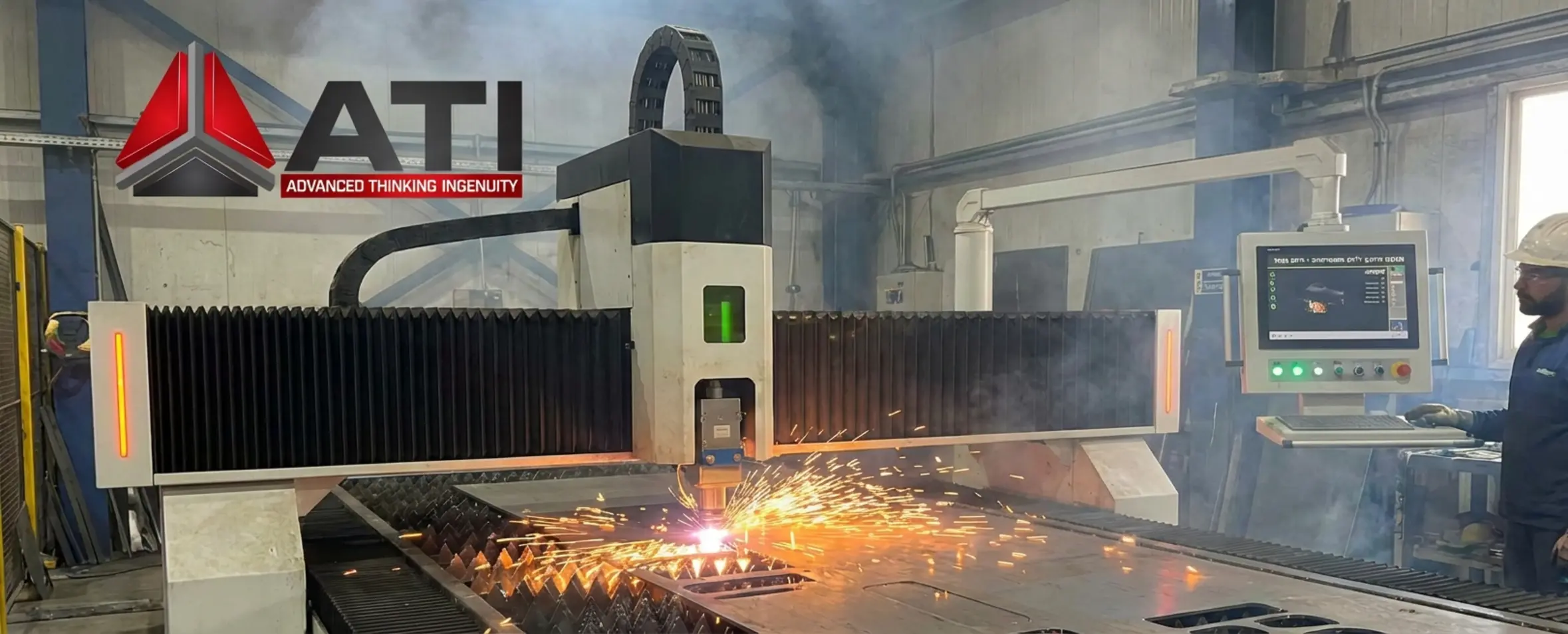
The Holy Trinity: Cutting, Bending, and Finishing
The manufacturing process of a metal enclosure consists of several chronological stages, each requiring precise engineering planning.
1. Cutting and Punching
The first step is converting the flat sheet (called the "flat pattern") into the required geometric shape before bending. There are two main methods:
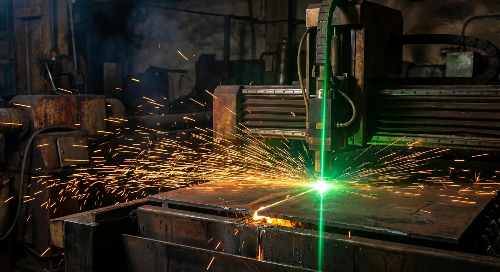
- Laser Cutting: The most common and precise method today. A powerful laser beam cuts the metal with accuracy of tenths of a millimeter. The advantage is no physical contact between tool and material, preventing distortion, and the edge finish is very clean. Ideal for prototyping and small to medium production runs.
- Punching (Turret Punch): A machine using a series of punches to create holes and shapes. This method is highly efficient when the enclosure has many ventilation holes (grille) or when embossing is required (such as creating threads or sheet raises) during cutting.
2. Bending
After cutting, the flat part moves to the bending machine (Press Brake). This is where the product designer's knowledge comes into play. The machine applies enormous pressure on the sheet against a bottom die and top punch to create the desired angle. In this process, the Bend Allowance (bending addition) and Springback (the metal's tendency to spring back slightly after bending) must be taken into account.
3. Hardware Insertion (Inserts)
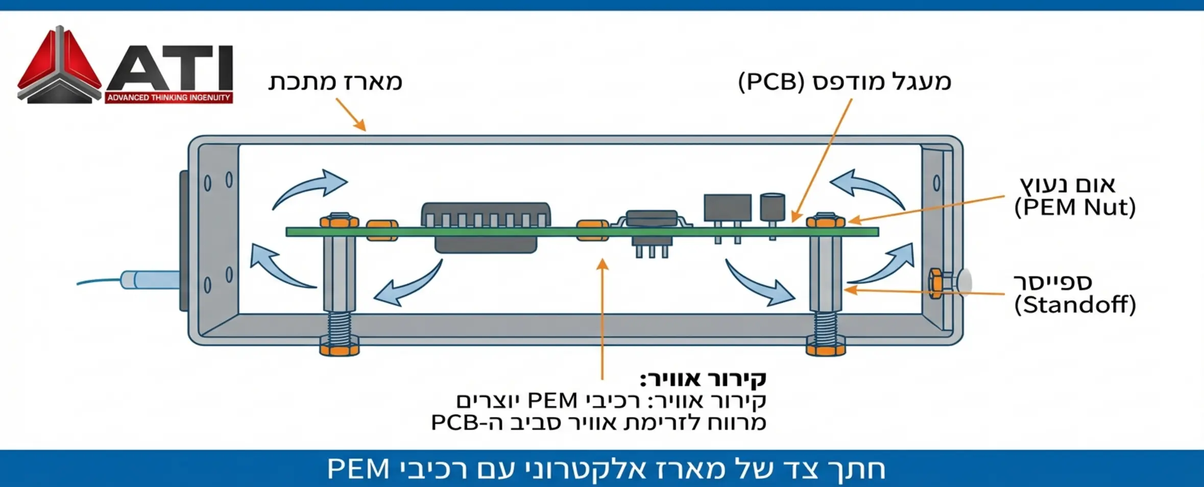
One of the fundamental differences between a simple "tin box" and a professional electronic enclosure is the use of fastening hardware. In thin sheets (e.g., 1 - 1.5 mm), it's difficult to create strong threading that will hold up. For this purpose, a press machine is used to secure PEM-type nuts, screws, and standoffs. These allow easy mounting of the PCB (Printed Circuit Board) inside the enclosure.
Proper Enclosure Design for Electronic Products
When approaching the task of designing a sheet metal-based product, there are several iron rules that will keep costs low and quality high.
Raw Material Selection
The material choice affects weight, cost, heat dissipation, and finish:
- Aluminum (5052 or 6061 series): Lightweight, excellent heat conductor (very important for electronics), doesn't corrode easily, and is easy to machine. Preferred material for airborne or portable enclosures.
- Steel (CRS / Cold Rolled Steel): Strong, relatively inexpensive, but requires protective coating (like painting or galvanization) to prevent rust. Very common in industrial computer enclosures.
- Stainless Steel (304/316): Expensive and difficult to machine, but offers absolute corrosion resistance and a premium look without paint. Mandatory for medical or food equipment.
Thermal Management
Electronic products generate heat, and the enclosure must dissipate it. In sheet metal design, dedicated ventilation openings can be integrated at no significant additional cost (during laser cutting). In cases where the processor or power components are mounted against the enclosure wall, the sheet itself serves as a heatsink. In such cases, aluminum is chosen and paint is avoided at contact points to ensure optimal heat transfer.
Powder Coating and Finishes: Not Just Aesthetics
The finishing stage determines the final appearance of the product and its durability over years. The most common method is Powder Coating. In this process, electrostatic powder is sprayed onto the part, which then enters an oven at approximately 200°C. The powder melts and forms a hard polymeric layer that is highly resistant to scratches and impacts.
Important to remember: paint is an electrical insulator. In electronic enclosures, electrical conductivity between enclosure parts is often required for grounding and electromagnetic shielding (EMC/RFI). Therefore, areas without paint (Masking) must be defined in the drawing, or conductive coatings such as Alodine for aluminum should be used before or instead of painting.
Sheet Metal vs. Plastic Injection Molding
| Feature | Sheet Metal (Bending) | Plastic Injection Molding |
|---|---|---|
| Setup Cost (NRE) | Very low (no molds) | Very high (tens of thousands of dollars per mold) |
| Design Flexibility | Very high (file change only) | Low (requires physical mold modification) |
| Mechanical Strength | Very high | Medium (depends on material and design) |
| EMI/RFI Shielding | Natural (Faraday cage) | Requires special expensive coating |
| Economic Viability | Prototype to thousands of units | Mass production (tens of thousands and up) |
Common Design Mistakes in Enclosure Design
As a company guiding numerous entrepreneurs through the manufacturing process, we encounter recurring mistakes that can significantly increase production costs:
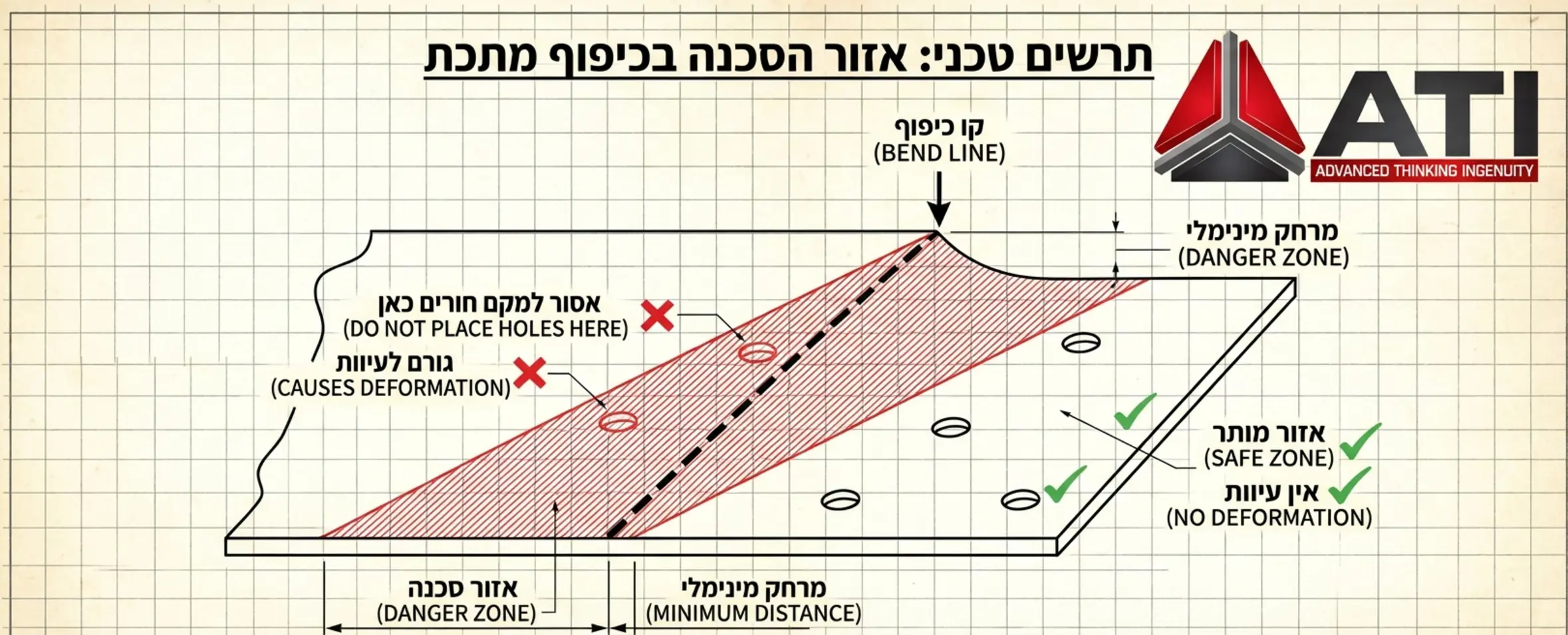
- Holes too close to bends: When a hole is positioned too close to the bend line, it may deform during pressure. A minimum distance defined as a function of material thickness must be maintained.
- Non-uniform bend radius: It's recommended to design all bends in the product with the same internal radius to avoid tool changes on the machine (Set-up), saving time and money.
- Not accounting for coating thickness: Powder coating adds approximately 60 to 100 microns to part thickness. If the design has zero tolerance, parts won't fit together after painting.
From Development to Production: The Transition to Industry
The great advantage of working with enclosure experts is the ability to take a 3D CAD file and turn it into a finished product in a short time. The development process at ATI includes feasibility checks and DFM (Design For Manufacturing) analysis before the laser makes the first cut. This is a critical stage where we verify that the enclosure not only looks good on the computer screen but can also be efficiently mass-produced, is easy to assemble by production line workers, and meets the required standards.
According to data from the international standards organization NEMA, meeting sealing standards (such as IP65 or NEMA 4) requires advance planning of gasket channels and continuous welds - elements that must be defined at the initial sheet metal drawing stage.
Summary
The metal enclosure is the home of your product. Proper design using sheet metal technology enables creating durable, aesthetic, and functional products while maintaining a reasonable budget and operational flexibility. The combination of precision laser cutting, smart bending, and quality powder coat finishing gives the final product the premium feel that customers are looking for.

Tip From the Experts
In the hardware world, the enclosure is the business card of the technology inside. Investing in smart enclosure design that considers both aesthetics and human engineering and assembly is the difference between a product that looks 'homemade' and a leading industrial product.
Key Takeaways
No Expensive Tooling
Unlike injection molding, sheet metal requires no costly molds - design changes are just file edits.
Thermal Management
Metal enclosures naturally dissipate heat - aluminum even serves as a heatsink for electronics.
EMI/RFI Shielding
Metal enclosures form a natural Faraday cage, protecting electronics without special coatings.
The Holy Trinity
Cutting, bending, and finishing - three sequential stages that transform flat sheets into 3D enclosures.
PEM Hardware
Press-fit nuts, standoffs, and screws enable professional PCB mounting in thin sheet enclosures.
Powder Coating
Oven-cured electrostatic powder creates a durable, scratch-resistant polymeric finish layer.
Frequently Asked Questions
What's the difference between galvanized steel and stainless steel in electronic enclosures?
The main difference is in corrosion resistance and price. Galvanized steel is regular steel coated with zinc to prevent rust. It's cheaper, easy to machine, and magnetic, but requires painting for a perfect aesthetic finish and isn't suitable for extreme environments over long periods if the coating is damaged. In contrast, stainless steel contains chromium and nickel that provide natural corrosion resistance through the full depth of the material. It's significantly more expensive, harder to bend and machine, but doesn't require paint and is suitable for sterile or wet environments.
What sheet thickness is recommended for a standard electronic enclosure?
Sheet thickness depends on the enclosure size and the weight of components inside. For small to medium enclosures (like routers or converters), 1.0 mm to 1.5 mm in aluminum or 0.8 mm to 1.2 mm in steel is most common. This thickness provides sufficient structural strength without adding unnecessary weight. For larger enclosures (like 19" server racks), 1.5 mm to 2.0 mm is typical to prevent bending under load.
How do you ensure the enclosure is water and dust sealed (IP rating)?
To achieve a high sealing level (e.g., IP65 and above) in sheet metal bending technology, simply bending the metal isn't enough. Continuous welds (not spot welds) must be designed at the enclosure corners to close gaps. Additionally, a dedicated "lip" or channel must be designed where a rubber or silicone gasket is placed, so when the cover closes, it presses on the gasket and creates a hermetic seal. Using sealed PEM hardware (blind standoffs) also prevents liquid penetration through screw holes.
Can curved and complex shapes be made with sheet metal bending?
Standard bending technology (Press Brake) primarily produces straight lines and sharp angles. However, large radii and curves can be achieved through a process called "bump bending," where the machine performs a series of very small, closely spaced bends that create the illusion of an arc. For more complex three-dimensional shapes that cannot be unfolded flat, deep drawing technology is required, which needs a dedicated and more expensive die.
What is K-Factor and why is it important in design?
The K-Factor is a critical mathematical value in calculating the part's flat pattern. When bending metal, the inner side of the bend compresses and the outer side stretches. The K-Factor represents the position of the neutral axis in the material that doesn't change in length. If the designer doesn't correctly define the K-Factor in the CAD software, the flat pattern sent to the laser will be too long or too short, and the final dimensions of the enclosure after bending won't be accurate, causing assembly misalignment.
Can powder coating interfere with device grounding?
Yes, absolutely. Powder coatings are electrically insulating polymeric materials. If the entire enclosure is painted, there will be no electrical contact between the cover and body or between screws and the chassis, preventing proper grounding and electromagnetic shielding (Faraday cage). The solution is to define masking areas in the drawing - points where heat-resistant tape is applied before painting and removed after, leaving exposed metal for electrical contact at connection and grounding points.